Contactor Jewelry: Precharge Resistors & Spike Suppression Diodes
Zero Emission Vehicles Australia
 |
 |
Contactor Jewelry: Precharge Resistors & Spike Suppression Diodes
|  |
7th August 2008
|
Introduction
While contactors will work fine by themself, there are a couple of useful accessories you can add to your contactors to improve their service life, and to avoid damage to themself and associated components: Precharge Resistors and Spike Suppression Diodes. Not many people are familiar with their use or function, but the good news is they are really simple to build and install. Here's how..
What You Will Need
All the parts you'll need are available from local electronics shops (other than the contactor itself!)
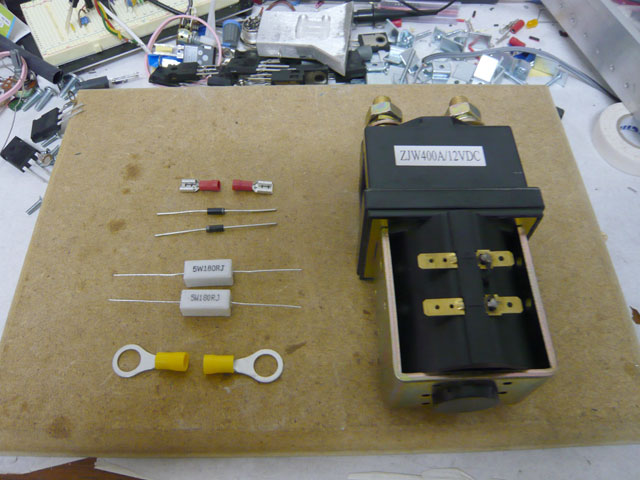
Parts for Precharge Resistors:• 5W ~1Kohm resistor x 2
• 10mm Ring Terminals x 2
Parts for Spike Suppression Diodes:• 15V 5W Zener diode e.g 1N5352B x 2 (Jaycar cat# ZR-1450)
• 6.4mm Female Spade Lugs x 2
• ~6mm diameter heatshrink tube (optional)
Tools:
• Pliers
• Soldering Iron & solder
• Heat gun (for heatshrink)
|
|
Precharge Resistors
The job of the main contactor in an EV is to connect and disconnect power from the batteries to the motor controller. Motor controllers have a large internal bank of capacitors for handling ripple current (i.e smoothing the flow of power from the batteries), which has a very low resistance. As a result, if a battery is suddenly connected to a motor controller, there is a huge inrush of current to the controller as it charges the internal capacitors - often over 1000 amps! This current spike can cause problems both for the batteries and the contactor, since it may be well above their rated load.
The easy solution to this is to connect a precharge resistor across the contactor, which will allow a small amount of current to flow to the motor controller while the contactor is off - enough to slowly charge the capacitors, but not enough to let the car go anywhere! Appropriate resistance value varies with voltage and is not critical, but 5-10 ohms per volt is typical, and rated to about 10 watts.

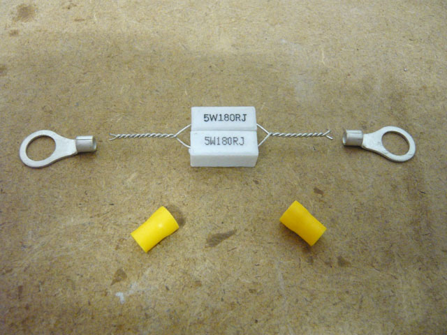
You can twist the resistor leads together for neatness .The plastic insulation can be pulled off the terminals to allow for soldering .
|

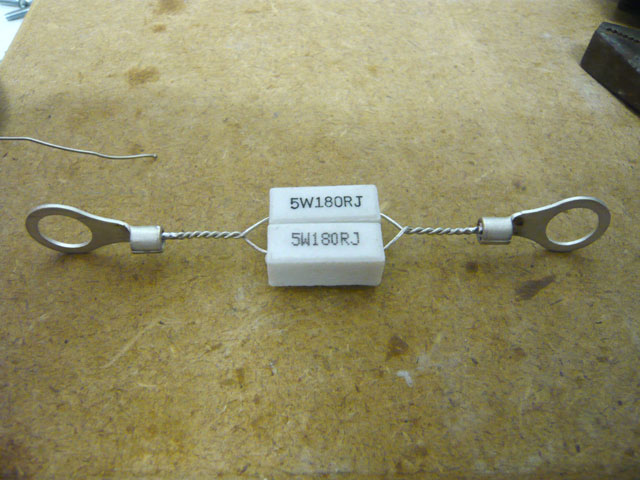
Then the ring terminals are soldered to the leads of the resistors as shown above .
|

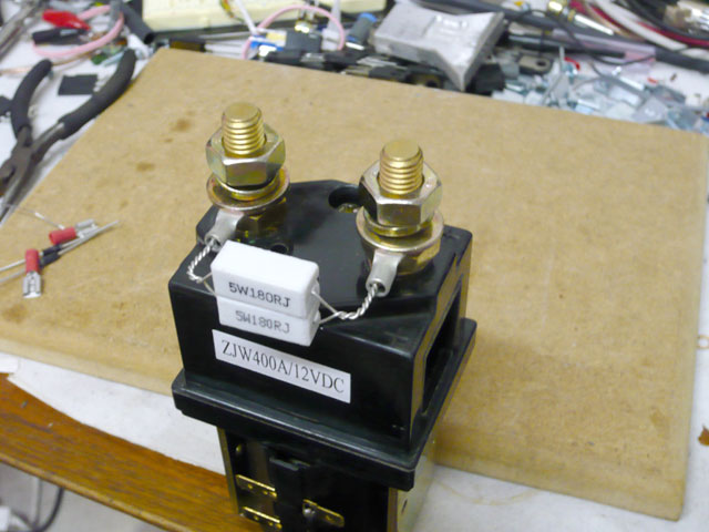
You can bend the legs around so the rings fit onto the contactor terminals . Ideally mount them under the main washer so the spring washer doesn't damage the ring terminals .
|
NOTE: This is the most basic way to set up a precharge system. A superior system is to only enable the precharge for a few seconds before closing the main contactor, instead of having it constantly enabled as shown here. Usually this requires some extra circuitry for controlling the two stage process (switch on precharge, then main contactor) but is highly recommended if you have the skill to implement it!
Spike Suppression Diodes
Contactors have an electromagnet / solenoid for closing the contacts when energised. The coil in these is an inductive load, which means you can't change the current flowing through them instantly. If the power source which is energising the coil is suddenly removed, the coil generates a voltage spike (in an effort to maintain current flow) while its magnetic field is collapsing. This can be far higher than the 12V used to drive the coil, and can result in damage to external devices such as your ignition relay etc.
To avoid this, you can attach Zener diodes across the connections to the coil.For the unfamiliar, Zener diodes block the flow of current in their reverse direction up to a specific voltage, beyond which they freely allow the flow of current. So by using two Zener diodes back-to-back, they can recirculate any voltage spikes and prevent excessively high voltage from reaching external devices.

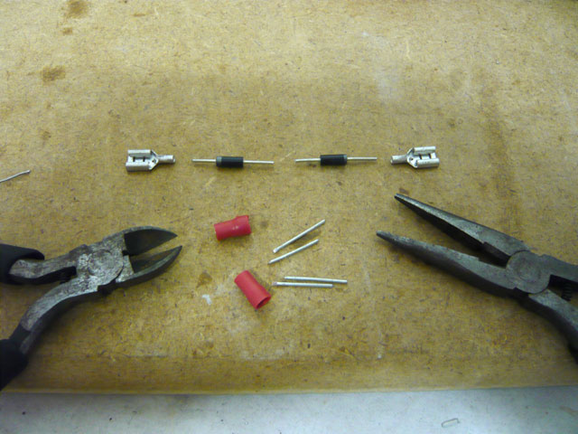
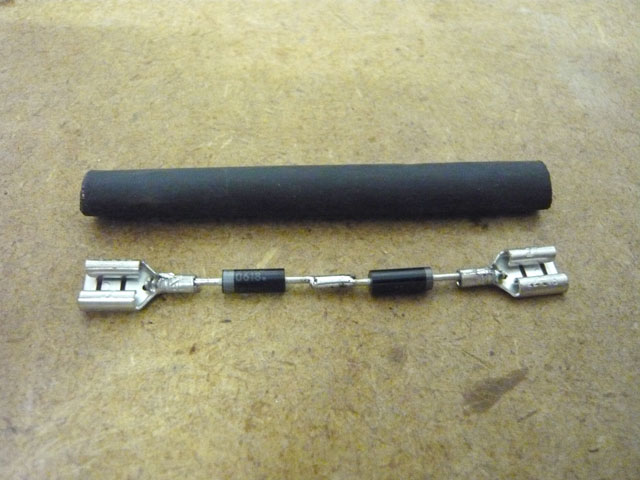
Trim the legs of the zener diodes down to about 10mm in length . The plastic insulation can be twisted off the spade lugs to allow for soldering .
|

Here you can see the four parts soldered together . Be sure to have opposite polarity with the zener diodes .Optionally, you can add heatshrink over the assembly for insulation .
|

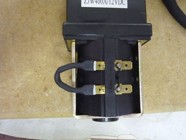
You can bend the assembly into a U shape to attach it to the spare set of spade terminals on the contactor .
|
2011 Update
ZEVA now manufactures an automatic precharger with built-in spike suppression diode
. The device enables a precharge resistor then switches the contactor when it detects precharge completion (rather than having the precharge resistor permanently in-circuit, as described above)
. For more information please visit the
Products page
.