12/10/2014

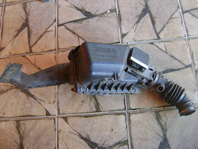
Retirando o motor do Vectra

ATUALIZAÇÃO 16/03
Video mostrando a retirada do motor e da caixa


Vamos começar a retirada do motor do Vectra.
No princípio apenas alguns conectores para se verificar o nível de dificuldade e as ferramentas que serão necessárias.

Este manual de reparação do Vectra pode ajudar muito esta tarefa.

Haynes Opel Vectra B 1995-1999 Repair and Manual-2.pdf

Vamos lá:


Parece que o melhor é retirar o motor por baixo, retirando o sub-frame inteiro. O Vectra deve estar com a frente bem levantada para que o sub-frame saia pela frente e por baixo.

Estes passos eu peguei no forum do Calibra:


If you have the space, the out the bottom is by far the easiest. Taking the inlet manifold off helps reduce the clearance needed by a few inches.

Disconnect everything from the engine and gearbox form the top, connectors, hoses, pipes, etc.
Undo the driveshaft nuts. Split the bottom ball joints. Exhaust front pipe off.
Unbolt the subframe. Support the engine, unbolt the engine mounts. 
Lower it all down as one piece.

You may want to renew, lower arms, track rod ends and arg bushes while it's all apart and easy to get to.

I've assisted a mate with the same job on a Vectra B twice (2.5 to 2.5 and 2.5 to 3.2)

Easiest way is definitely dropping engine plus subframe together through bottom, the first time we tried to lift and drop engine from top we had nothing but trouble.

Take photos before disconnecting cables, pipes, hydraulics, sensors etc so you know how it goes back together.

On Vectra B you just needed to undo top suspension mount, remove brake calipers, disconnect steering (on Calibra think it'd just be track rod ends as the steering rack on Vectra completely different i.e. not on bulkhead), unbolt exhaust at downpipe and then just pipes/cables etc finished by undoing the subframe / chassis bolts.

We used an engine crane both times, letting subframe sit on the crane legs made it easier to wheel around then work on swapping block/engine safely.

Obviously drain oil and coolant.

Any screws, washers, nuts etc you remove put into labelled pots / tubs to help with reassembly.

Remove all the quick parts like inlet manifold, battery etc as it just helps you access all the bit you're going to need to reach.

When dropping engine definitely do it slowly with an 'assistant' constantly checking all around as chances are you'll forget to disconnect or undo something (we forgot the alternator to battery wiring plus starter motor).

As mentioned already renew any other serviceable items and parts on the front suspension.

Worthwhile giving the engine bay a quick clean and rust treatment / repair whilst it's empty, my mate didn't want to do this for some reason!

Sub frame

Cano de descarga

Detalhe de um ponto de fixação do sub frame

Detalhe do protetor de carter rasgado

Dificuldade para desaparafusar este ponto. Chave canhão de 13mm

Sonda Lambda

Detalhe de um ponto de fixação do cano

Detalhe homocinética


Cano no chão

Sem o coletor do escapamento

Abriu mais espaço para desaparafusar outras coisas


Lateral sem o parachoque

Boa visão


10/10/2014

Comparação entre os preços dos kits HybridPack1 e PIN FIN e respectivos módulos

Possibilidade de compra imediata do Kit Pack1 e posteriormente a troca do módulo de potência.

Kit Hybrid PACK1: €1.370,00 = R$ 4.110,00
Módulo FS400R07A1E3: $ 336,86 = R$ 808,46

Kit Hybrid PACK 1 PIN-FIN: €2.150,00 = R$ 6.450,00
Módulo FS400R07A1E3-H5: $ 462,29 = R$ 1.109,50


Fornecedores:
http://ehitex.com/application-kits/infineon/431/hybridkit1
http://www.eciaauthorized.com/search/FS400R07A1E3-H5
http://www.digipart.com/part/FS400R07A1E3-H5
http://ciiva.com/part/fs400r07a1e3-h5-13022451
http://br.mouser.com/ProductDetail/Infineon/FS400R07A1E3_H5/?qs=%2fha2pyFaduhobZpgNhHi9brWLSZRjh7sS58x8HxtSikWmw6zEriB1A%3d%3d

 € 1,00  = R$ 3,00
U$ 1,00 = R$ 2,40

Sugestão de compra: 
Kit Hybrid Pack1 = R$ 4.110,00
Módulo FS400R07A1E3-H5 = R$ 1.109,50

Total = R$ 5.219,50

09/10/2014

Reliable IGBT Power Semiconductor Modules for Hybrid Electrical Vehicles

Reliable IGBT Power Semiconductor Modules for Hybrid Electrical Vehicles

fonte: Power Guru
Free Bodo's Power Magazines!

Hybrid drives today have the potential to save energy in the automobile.

A main component of the hybrid system is the electric drive combined with the internal combustion engine. Significant attention needs to be given to the design of the power electronics according to the requirements arising from the various operating conditions as well as with regard to the ambient conditions in the vehicle.
By Ingo Graf, Infineon Technologies
Contrary to industrial applications, integration into the vehicle leads to other partially higher requirements. Ambient and system conditions such as strong vibrations, high temperatures, transient loads, high power density or a high number of load cycles impact significantly on the design and application of possible semiconductor concepts. Only one limiting factor here is the restricted space available in the vehicle.
Conditional on the various installation positions in the vehicle suitable semiconductor concepts such as power semiconductor modules need to be developed. Figure 1 shows the typical construction of a power semiconductor module.
Construction of a power semiconductor module with DCB technology
Quality level and lifetime of the components used are the same for the hybrid system, while the ambient conditions for the various components can be very different. Hence the requirements for temperature and load cycle robustness of the power electronics are different. Cooling system and installation position can be simplified and categorized according to Table 1.
Requirements on the power electronics depending on installation position
High demands with regard to reliability are placed on the bond wire connections in the components. The operating load changes in the aluminium wire (power cycles) and the differing coefficients of expansion of silicon and aluminium result in micro-movements in the material. This may lead to small cracks in the connection points, the so called “Bond Wire Lift Off”. In effect the component may fail.
During its lifetime the connection point between silicon and bond wire will endure several million load cycles. Depending on the temperature rise ΔT taking effect on the semiconductor, a number of power cycles will be achieved accordingly. Generally, the number of possible load cycles reduces with increasing ΔT.
A significant influence on the load cycle capability is the temperature level of the component. Fluid cooled power electronics in hybrid drives will, other than air-cooled systems, reach heatsink temperatures of more than 100°C. For semiconductors with a permissible junction temperature of Tj = 125°C (continuous operation) this will only leave little headroom for temperature rise. Thus semiconductors with higher junction temperatures are required for hybrid systems.
An increase of the junction temperature by 25 K reduces the possible load cycles by a factor of two. When introducing the Infineon designed 600V IGBT³ and the EmCon3 diode, measures had to be taken both in chip design as well as in packaging of the semiconductor module, to achieve the same cycling capability at the increased junction temperature of 150°C.
Figure 2 shows the possible number of cycles (power cycling graphs) for various temperature levels (Tj: junction temperature of the semiconductor) at various temperature fluctuations ΔTj. The number of load cycles of the 150°C curve (600V IGBT³) achieves the same number of possible load cycles at the same temperature rise as the 125°C graphs (600V IGBT²). In other words, this equates to an improvement of the load cycle capability for the 600V IGBT³ chip by a factor of two, referenced to a junction temperature of 125°C.
Power cycling graphs for power semiconductor modules 600V IGBT³ vs 600V IGBT²
Over the lifetime of direct copper bonding (DCB) modules the layers are prone to recurring mechanical stress, due to the ongoing thermal cycles. Caused by the current flow in the semiconductor and the resulting heat up, the materials used such as copper, ceramics, silicon and aluminium expand with their different coefficients of expansion.
This may lead to premature solder fatigue between the DCB substrate and the baseplate. The result is delamination of the solder layer and the increase of the thermal resistance caused by this. Finally, the component fails due to overheating.
For industrial applications usually modules with a standard DCB (Al2O3) in conjunction with a copper baseplate are used, as the requirements for thermal cycling capability are much lower here than in traction applications for example. For these often a combination of materials is used consisting of an AlN DCB and an AlSiC baseplate.
An important qualification test for semiconductor modules is the so called thermal shock test (TST). In this two chamber test the module is permanently exposed to temperature fluctuations of -40°C to 125°C (or 150°C) and from 125°C (or 150°C) to -40°C. After the test with a predetermined number of cycles the degree of solder layer delamination between baseplate and DCB is evaluated.
Power semiconductors for hybrid drives bear requirements of up to 1000 cycles of thermal shock. This requirement can not possibly be achieved with a standard DCB module construction. One solution would be the use of the material combination mentioned above – AlN DCB with AlSiC baseplate. This approach, however, results in added material cost and is suitable primarily where the heatsink temperature is already at a very high level. As can be seen in Figure 3, the degree of solder layer delamination is unchanged even after 1000 cycles for this combination of materials.
Ultrasonic scan of solder delamination after TST for AlN DCB and AlSiC baseplate
Considering the temperature fluctuations and number of required thermal cycles during the lifetime, a cost optimised solution has to be found for the power semiconductor concept. One solution is the use of a so called “improved” Al2O3-DCB in conjunction with a copper baseplate. This combination of materials is mainly suitable for mild hybrid systems and some full hybrid systems. Figure 4 shows clearly that an “improved” DCB contributes to a much advanced thermal cycling capability.
Ultrasonic scan of solder delamination after TST for Al2O3 - DCB on copper baseplate
When designing the power semiconductor module particular consideration needs to be given to the load profile during the lifetime of the hybrid vehicle. Once the required profiles are available detailed in passive temperature fluctuations and current profiles, a suitable combination of materials substrate (DCB) / baseplate can be determined.
The following hypothetical example (Table 2) depicts, for a supposed annual temperature profile, what influence different combinations of materials and/or construction techniques will have on the thermal cycling capability, considering various cooling conditions. The assumed temperature rise delta Tc (temperature rise of the baseplate) is the reference value for the lifetime consideration. Assuming that the percentage of used available lifetime can be accumulated, the final value is then determined. If the final value exceeds 100%, the selected module solution (combination of materials / construction techniques) is insufficient for the assumed conditions in this application. Failure of the power electronics will occur before the required lifetime has expired.
Hypothetical scenario “thermal cycling capability” for a) air cooling
Hypothetical scenario “thermal cycling capability” for b) fluid cooling
The scenario depicted (Table 2) indicates that the use of a slightly different combination of materials / construction techniques of DCB substrate and baseplate may be sufficient for an air-cooled semiconductor module. A high-end solution is not the best in these cases as unnecessary expenditure results. The gain in performance can not be utilized (over-design).
It can be shown that in water cooled systems with high temperature levels the use of high-end combinations of materials / construction techniques can satisfy the requirements for the lifetime expectation (Table 2b).
Infineon has developed new power semiconductor modules for mild and full hybrids. The modules are equipped with the latest 600V IGBT³ chip technology for a Tvjop = 150°C and an improved bond process is used. The load connections feature screw terminals. The auxiliary connections are brought out as solder terminals and moulded into the plastic case.
The cost optimized HybridPACK™1 module (FS400R06A1E3) has been developed for 20 kW applications. This module features a SixPACK configuration with 400A / 600V switches and is intended for the use in mild hybrid with forced air-cooling. The module is equipped with an NTC (temperature monitoring) and is constructed with an “improved” Al2O3 -DCB and a 3 mm copper baseplate. The size of the baseplate is 139 mm x 72 mm.
HybridPACK™1 module (SixPACK 600 V-400 A)
Another development is the HybridPACK™2 module (FS800R06A2E3) for the power range above 50 kW. This module has been specifically developed for fluid cooled systems (full hybrid) and is equipped with an AlSiC-PinFin baseplate. The chip current realized is 800 A per switch. Additionally, improvements regarding vibration robustness have been made.
HybridPACK™2 module (SixPACK 600 V-800 A)


First solutions for hybrid drives are now available with the modules introduced here as part of the HybridPACK™ product family. Further developments will follow.

Análise do kit HybridPACK1 e HybridPACK1 PIN-FIN da Infineon

   A Infineon também possui outros dois kits de desenvolvimento que são menos potentes, mas que também são mais baratos.
   São kits para o desenvolvimento de aplicações, pode-se comprar no máximo 3 kits.

Trata-se dos kits:  HybridPACK1 (para uma conversão híbrida em paralelo) e HybridPACK1 PIN-FIN (para uma versão híbrida em série ou totalmente elétrico).

   A diferença destes dois caras além do preço é claro, é que o PIN-FIN vem com uma espécie de dissipador de calor diferente, são uns pinos que em contato com a água da refrigeração líquida, faz com que o módulo de potência (é o mesmo pros dois kits) se resfrie mais rápido. Com isso a potência nominal salta de 20kW (30kW pico) para 40kW (50kW pico).

   Vamos a algumas figuras:

   Esta é a caixa da embalagem, pode-se ver embaixo à direita o inversor completo.

   Inversor completo.

Dimensões.

   O bloco azul/branco é o capacitor do link CC.


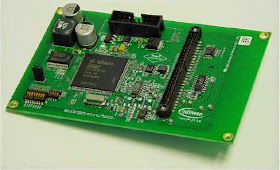
A plaquinha menor é o módulo lógico, as funções lógicas do inversor estão aqui.

A placa maior é o módulo do driver de potência.


Nesta placa esta aparafusado/soldado o módulo de potência:
Embaixo do módulo de potência esta o dissipador de calor refrigerado à água cooling fluid = 50% water/50% ethylenglycol. Este dissipador já vem nesta versão.

Na versão PIN-FIN, é necessário fazer o dissipador, mas existe uma sugestão de projeto para ele no manual de instruções.

Segue explicação da vantagem deste tipo de dissipador.